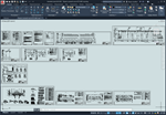
Project of the power section of the KTP AVO gas
Content: 00043_file.rar (1.40 MB)
Uploaded: 02.10.2024
Positive responses: 0
Negative responses: 0
Sold: 0
Refunds: 0
$0.38
Working project of the integrated transformer substation of the gas air cooling unit.
The gas air cooling unit is designed to supply electric motors of the fans of the AVGB-83 type gas air cooling units. Power supply reliability category; - II. A complete transformer substation with two 10/0.4 kV transformers with a capacity of 1000 kVA with 10 kV input cabinets and a two-section low-voltage switchgear with an ATS between the sections is accepted for installation.
The power of the transformers is taken based on the operation of the gas cooling units in the maximum mode - 11 working.
Control cabinets supplied as a set are accepted as starting and protective equipment for the fan electric motors.
Local control of the fans is provided.
Capacitor units of the KRM-0.4 type are used to compensate for reactive power.
Composition of the design documentation of the integrated transformer substation of the gas air cooling unit:
1. General data.
2. 2-KTPP-1000/10/0.4-84-UZ. Schematic electrical diagram.
3. SR, SR2. Schematic diagram of the power supply network -380/220V.
4. SR4. Schematic diagram of the power supply network =220V.
5. Electric furnace PET-4 (NE1-NE4). Schematic diagram of the control circuit.
6. Electric furnace PET-4 (NE9-NE10). Schematic diagram of the control circuit.
7. Cabinet (ShU1-ShU13) for controlling the fans of the gas AVO. Electrical connection diagram.
8. Layout plan of electrical equipment.
9. Power supply of furnaces NE1-NE10 and fans B1, B2.
10. Layout and cable routing plan.
11. Grounding. Plan.
12. Electric lighting. Layout plan of electrical equipment and cable routing.
File format: dwg, tif (AutoCAD 2010 not editable)
Note: source files of *.tif format must be in the same folder with the project file *.dwg
Download file "Project of power section of KTP AVO gas" >>>
Tags: gas compressor station, AVO gas
No feedback yet
