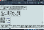
Project of water supply and sewerage networks KS
Content: 00021_Проект сетей водопровода и канализации КС.rar (1.65 MB)
Uploaded: 16.09.2024
Positive responses: 0
Negative responses: 0
Sold: 0
Refunds: 0
$0.38
The following systems have been designed by the working documentation:
- underground water supply B9;
- fire-fighting water supply B2;
- domestic and drinking water supply B1;
- industrial water supply VZ;
- household sewerage K1;
- industrial sewerage KZ;
- storm sewerage K2.
The source of water supply and adjacent sites are two artesian wells (one working and one reserve), operating in turn. The wells are located on different sites BC1 and BC2. On site BC2, in addition to the pumping station above the artesian well, there is: a second-lift pumping station with a water purification unit, a drinking water reserve tank and an absorber filter.
The compressor station water supply project contains the following drawings:
- general data;
- explanatory note;
- underground water supply diagram;
- industrial water supply diagram;
- domestic and household sewerage diagram;
- detailing of water supply wells on sewerage networks;
- equipment specification.
File format: dwg, tif (AutoCAD 2010 not editable)
Note: source files of *.tif format must be in the same folder with the project file *.dwg
Download file "Project of water supply and sewerage networks of the compressor station" >>>
Tags: gas compressor station, general plan
No feedback yet
